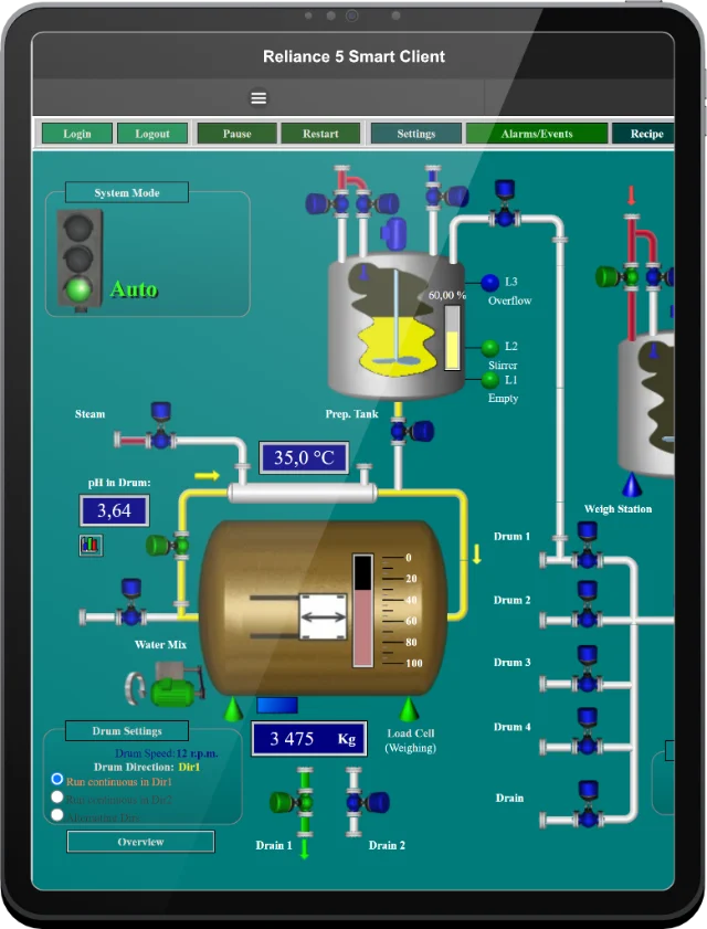
Modbus Communication Driver is intended for data connection between Reliance's runtime software and devices communicating via the Modbus RTU and/or Modbus TCP communication protocols. The driver implements basic communication functions for reading and writing data in both the Client mode and the Server mode.
Supported Reliance versions
The communication driver is supported in both Reliance 5 and Reliance 4.
01 Read Coil Status – reading digital outputs
02 Read Input Status – reading digital inputs
03 Read Holding Registers – reading holding registers
04 Read Input Registers – reading input registers
05 Force Single Coil – writing a single digital output
06 Preset Single Register – writing a single holding register
15 Force Multiple Coils – writing multiple digital outputs
16 Preset Multiple Registers – writing multiple holding registers
20 Read General Reference – reading the extended memory
22 Mask Write 4X Register – mask writing a single holding register
01 Read Coil Status – reading digital outputs
02 Read Input Status – reading digital inputs
03 Read Holding Registers – reading holding registers
04 Read Input Registers – reading input registers
05 Force Single Coil – writing a single digital output
06 Preset Single Register – writing a single holding register
16 Preset Multiple Registers – writing multiple holding registers
If any of the writing functions is not supported by the device, this function can then be deactivated.
The desired channel type can be selected in the Reliance development environment's Project Structure Manager (device connection).

A Modicon M580 programmable logic controller
The communication driver is a DLL loaded into memory by the Reliance 4 Driver Server program, which can be launched either as a Windows service at Windows startup or as a standard application at the start of a visualization project. Information required to make a connection with devices is read from the visualization project. After reading this information, communication to all connected devices is activated.
Modicon systems' memory is divided into the following four basic areas: discrete inputs, discrete outputs, input registers, holding registers. In Modicon systems, these areas are addressed absolutely (see the "Modicon addressing" column in the table below). In the Reliance system, however, tags are addressed relatively always starting at zero (see the "Reliance addressing" column in the table below).
| Addressing tags in a Modbus device | |||
| Memory area | Modicon addressing | Reliance addressing | |
| Register type | Address | ||
| 1. Discrete outputs (Coils) | from 00001 | Outputs (Coils) | from 0 |
| 2. Discrete inputs | from 10001 | Inputs | from 0 |
| 3. Input registers | from 30001 | Input registers | from 0 |
| 4. Holding registers | from 40001 | Holding registers | from 0 |
In the Reliance system, a tag at 40011 will be addressed as follows: Register type: Holding registers; Address: 10
Data is read periodically based on the defined communication zones. The tag value and the data of the communication zone in which the tag is located are always updated together. The tag data type must match the size of a data point in the selected register type. The size of data points is defined by the Modbus protocol (Coils, Inputs – bool; Holding registers, Input registers – word).
The loss of connection is detected if the communication driver doesn’t receive a valid response Nx consecutively (N represents the maximum number of failed communications). This parameter can be adjusted.
For information about the price, please contact your local distributor.
If you have any questions, please feel free to email or call us.
Phone:
Info:
Sales:
Suppor:
Phone:
Info:
Sales:
Support:
Phone:
Info:
Sales:
Support:
GEOVAP
Cechovo nabrezi 1790
530 03 Pardubice
Czechia
© 2026 GEOVAP | Terms of Use and Privacy Policy | Cookie preferences | Write to us