In 2012, a new biogas power plant was put into operation by the agricultural cooperative in the small town of Mrakov.
The cooperative farms 2,500 hectares of land, about 1,000 hectares of which are meadows. Despite the large number of cattle, the cooperative was not able to process such a large amount of grass. Therefore, it was decided to build a biogas power plant that would allow for processing not only excess grass but also slurry, manure, and feed remains.
The input material (grass mixture, manure, corn, or silage) is first loaded to the Trioliet stationary mixer feeders. Using feed screws, the material continues to the Bio-Mix pump where the liquid component (slurry) is added. Then, it is piped to the chopper pump to be ground and, using a screw pump, to the fermentation tank. For greater homogeneity, the dilute material is mixed in the fermentation tank by submersible mixers and, at the same time, it is heated by the heat from the cogeneration unit. Fermentation is a two-stage process. It follows that there are primary and secondary tanks – fermenters. Biogas is collected in the gas holder. It is then compressed, dried, and subsequently combusted in the cogeneration unit. In addition to electric energy, the cogeneration unit generates heat that is used to heat the power plant buildings, stables, and other parts of the agricultural cooperative premises. Excess or low-quality gas is combusted in the auxiliary burner (flare). The entire process of fermentation is completed after about 30 days (depending on which material is used). The employed material is stored and used on fields as a substantial fertilizer. The fermentation process itself is continuous.

Mrakov Biogas Power Plant
In 2013, a heat exchanger was built to the biogas power plant. The exchanger takes the heat from the combustion products and uses it as a heat source for a nearby industrial complex.
Note: The following video was shot in Czech.
A distributed system is used to control the biogas power plant. Its central control unit is
a Siemens SIMATIC S7-300 PLC. It is located in the central control cabinet in the area of the cogeneration unit where it is connected to the adjacent actuators and sensors. The central unit is connected, via PROFIBUS, to Siemens SIMATIC ET 200M I/O modules that gather data from the actuators and sensors from other technological parts (input materials treatment, fermentation, slurry supply, gas collection and treatment). Finally, an operator station is connected to the system via Ethernet.
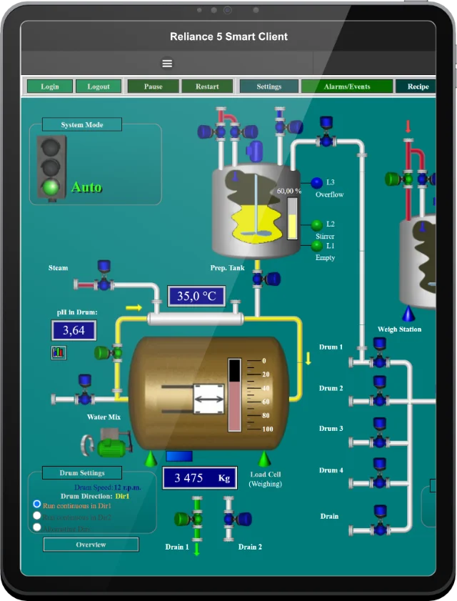
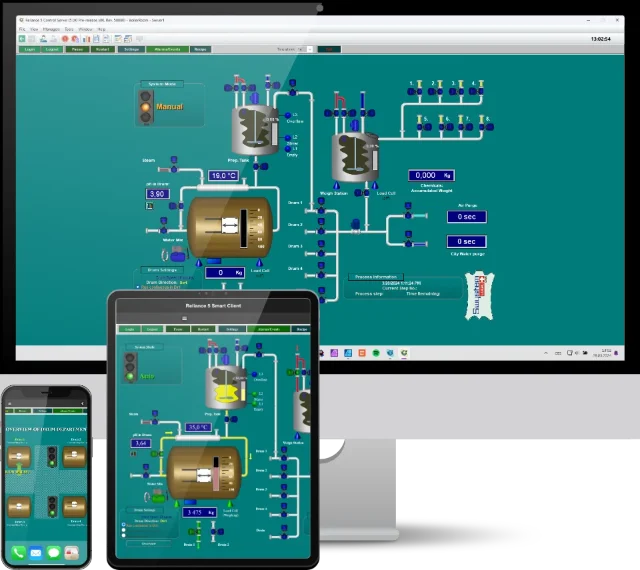
To clearly visualize and control the processes at the biogas power plant, the Reliance 4 SCADA/HMI system is used. It is installed on the operator's PC that allows for monitoring the entire process of biogas production. The operators can also access the visualization screens from remote locations using Reliance 4 Web Client. Sending email messages is another popular feature of the Reliance system that is also used. Some operators and service organizations are notified of the current status of individual processes via email messages. These advanced features allow the biogas power plant to operate automatically after working hours.

The starting overview visualization window

Visualization of the fermenters

Visualization of the gas management

Vizualizace procesu vytápění
The starting overview visualization window
Visualization of the fermenters
Visualization of the gas management
Visualization of the heating process
Country:
Title:
Implemented by:
Year:
Control system:
SCADA software:
If you have any questions, please feel free to email or call us.
Phone:
Info:
Sales:
Suppor:
Phone:
Info:
Sales:
Support:
Phone:
Info:
Sales:
Support:
GEOVAP
Cechovo nabrezi 1790
530 03 Pardubice
Czechia
© 2026 GEOVAP | Terms of Use and Privacy Policy | Cookie preferences | Write to us